First, let’s talk about the wiring. Daikin recommends a 16-18 gauge, stranded, non-shielded, two conductor wire. I have heard various comments including “why no shield” to “why not 18-8 thermostat wire”. Daikin communication is a 16vdc communication circuit. If we were to use shielded wire the shield would act as an antenna for transient voltage and can cause communication issues. Having said that, if you do install shielded wire, one end of each section of the daisy chain must be grounded to the fan coil chassis. Since DC voltage runs on the outside of the conductor it is not recommended to run solid thermostat wire as the surface area is minimal and can cause communication errors as well. Stranded wire has more surface area than a solid wire of the same gauge and provides for better communication.
The wiring on the Daikin communication network, known as the D-III network, runs in a daisy chain configuration from the outdoor unit to the indoor fan coils on a heat pump system or to the branch selector boxes on a heat recovery system. This is a very simple and flexible system using 16-18 gauge, stranded, non-shielded, 2 conductor wire that is not polarity sensitive on the daisy chain.

As you can see in the above picture the wiring is in a daisy chain from the outdoor unit to the indoor fan coils, this is typical of a heat pump system.
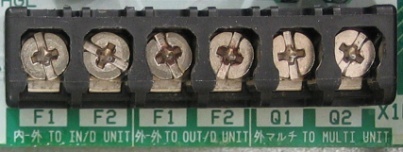
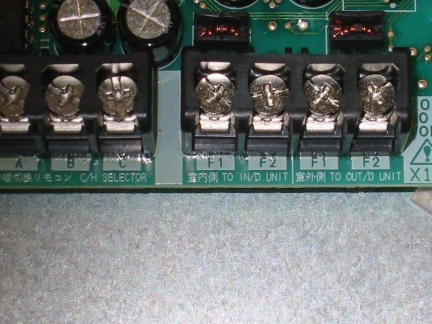
The connection points on the outdoor unit are labeled on the circuit board as F1F2 to IN/D unit, this will be your connection point to either the fan coils in a heat pump system or to the branch selector boxes in a heat recovery system. The branch selector connection points will be labeled F1F2 to OUT/D unit. On the outdoor unit you also have terminals F1F2 to OUT/D unit. These will daisy chain the outdoor systems to a centralized controller(Bacnet, LON, Itouch controller or Itouch Manager). The final terminals in the outdoor unit are Q1Q2 which connect multiple outdoor units on the same system together. If the system is a stand alone heat recovery outdoor unit the Q1Q2 is already installed from the factory. On the branch selector box terminal you will also have an F1F2 to IN/D unit these connect the branch selector box to the indoor fan coil.

Outdoor Unit Connections

Branch Selector Connections

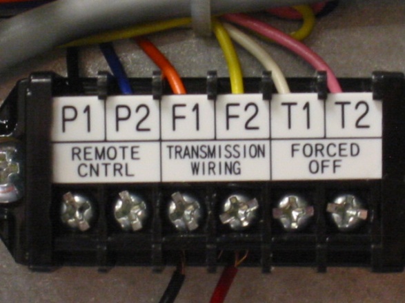
Indoor Unit Connections
Lastly on the indoor diagram above we have the P1P2 (Remote control) terminals, these will connect your remote controller (thermostat) to your fan coil.
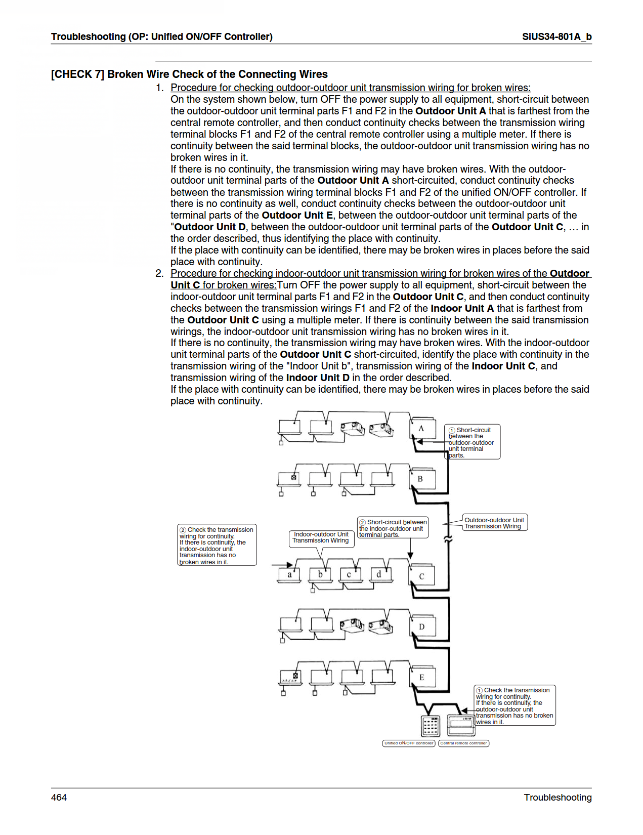
Diagnosing a communication problem or a U4 error code (U4 is loss of communication between outdoor and indoor units) can be labor intensive since the system cannot determine exactly where the loss occurred. We know that the system carries 16 vdc for its communication, so we need to find where that stops. The only way to do that is follow the daisy chain from the outdoor unit and check for 16 vdc at each termination point. This error typically occurs during the commissioning phase of the project and can be as simple as a terminal did not get tightened down or the insulation got nicked and the wire is grounding out. The following diagram was taken from the Daikin VRV III service manual and shows an alternate method of check continuity of the wire if you suspect a broken wire. More often than not the problem is a loose connection, the wire did not get striped correctly or there were improper splices in the wiring. Splices are highly discouraged in the communication lines but if they are necessary they must be done using the appropriate sized butt splice or soldered together and in both instances should have shrink tubing encasing the joint.


